Cornell University
School of Electrical and Computer Engineering
Diversity Programs in Engineering
CURIE Academy 2014
Design Project: Exploring an Internet of Things
Prof. Christopher Batten
237/239 Phillips Hall • July 13–19, 2014
home | details | schedule | lab1 | lab2 | lab3 | projects | handouts | photos | video | sponsors
The field of computer engineering is at the interface between hardware and software and seeks to balance the tension between application requirements and technology constraints. In the first lab session, scholars already became familiar with basic electrical circuits and explored the field of computer engineering from the hardware perspective by building a basic digital adder. In this lab session, scholars worked in groups of two to explore the field of computer engineering from a software perspective by incrementally building a mobile robot control application using the popular Arduino micro-controller. For detailed information about the lab see the following lab notes and handout. The lab notes review background information while the lab handout was used by scholars during the lab session.
Lab 2 Overview
Scholars started by compiling and running a basic Arduino program that simply adds two numbers together. By examining the compiled assembly code, scholars were able to see first-hand how high-level programming language constructs (e.g., +) are turned into low-level machine instructions (e.g., add instruction). Scholars then experimented with the light-emitting diodes (LEDs), switches, and potentiometers included as part of the mobile robotic platform, before testing the grayscale analog sensor and drive motors. Once scholars had a good feel for the basic sensors and actuators on the robot, they incrementally developed the full mobile robot control application in three steps: (1) develop a move-and-stop behavior; (2) develop wander behavior; and (3) develop a wander-to-target behavior.
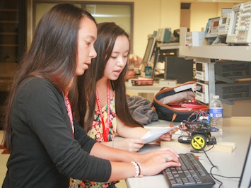
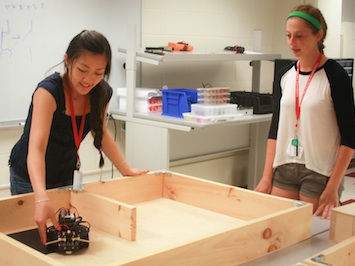
The following two photos show scholars working on the lab. The left photo shows two scholars beginning to program their robot using the Arduino development environment. The right photo shows two scholars testing their robots on the playing fields.
|
|
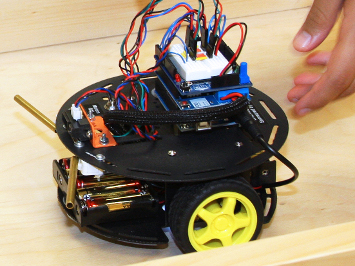
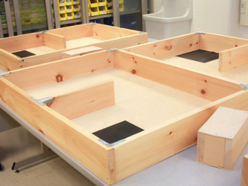
Lab 2 Hardware
To support the lab, we developed an Arduino-based mobile robotic platform using the DFRobot Turtle 2WD chasis, official Arduino motor controller shield, and the Maker Shed MakerShield Kit. We also added two mechanical bump switches and an infrared range finder for obstacle avoidance. Finally, we added an analog grayscale sensor to the bottom of the robot for detecting the target. We also built custom U-shaped playing fields measuring approximately 4'x3', with extra movable obstacles for advanced groups.
|
|
Lab 2 Software
We provided scholars with a simple template defining the appropriate
pin numbers and setup code. Scholars were responsible for writing
the loop function to implement their mobile robot control
application. The following code illustrates a simple solution to the
lab which causes the robot to wander the playing field, avoid
obstacles, and spin when it finds the target.
void loop()
{
  // Read mechanical bump sensors

  int bumped_left  = digitalRead( pin_bump_left );
  int bumped_right = digitalRead( pin_bump_right );

  // If robot has bumped into an obstacle, then backup and rotate

  if ( bumped_left or bumped_right ) {

    // Make robot go backwards
    digitalWrite( pin_motor_left_dir,  HIGH  );
    digitalWrite( pin_motor_right_dir, HIGH  );
    delay(1000);

    // Make robot rotate
    digitalWrite( pin_motor_left_dir,  LOW  );
    digitalWrite( pin_motor_right_dir, HIGH );
    delay(500);

  }

  // Read analog grayscale sensor

  int light = analogRead( pin_grayscale_sensor );

  // If robot is over the target, then spin and stop

  if ( light > 300 ) {

    // Make robot spin
    digitalWrite( pin_motor_left_dir,  LOW  );
    digitalWrite( pin_motor_right_dir, HIGH );
    delay(5000);

    // Make robot stop forever
    analogWrite( pin_motor_left_speed,  0 );
    analogWrite( pin_motor_right_speed, 0 );
    while (1);

  }

  // Make robot move forward

  digitalWrite( pin_motor_left_dir,  LOW  );
  digitalWrite( pin_motor_right_dir, LOW  );
  analogWrite( pin_motor_left_speed,  100 );
  analogWrite( pin_motor_right_speed, 100 );

}