Cornell University
School of Electrical and Computer Engineering
Diversity Programs in Engineering
CURIE Academy 2014
Design Project: Exploring an Internet of Things
Prof. Christopher Batten
237/239 Phillips Hall • July 13–19, 2014
home | details | schedule | lab1 | lab2 | lab3 | projects | handouts | photos | video | sponsors
The field of computer engineering is at the interface between hardware and software and seeks to balance the tension between application requirements and technology constraints. In Lab 1, scholars worked in groups of two to explore the field of computer engineering from a hardware perspective by gradually building a simple binary adder. For detailed information about the lab see the following lab notes and handout. The lab notes review background information while the lab handout was used by CURIE scholars during the lab session.
Lab 1 Overview
Scholars started by experimenting with resistors, light-emitting diodes (LEDs), and discrete transistors to implement a basic inverter and NAND logic gate. Scholars then learned how multiple transistors can be integrated into a single integrated circuit (IC) to implement other logic gates. Scholars tested ICs containing AND, OR, and XOR gates before composing multiple XOR gates to implement a four-bit parity checker. After a short lecture on binary arithmetic, scholars implemented a half-adder and then a full-adder capable of adding three one-bit values to generate a two-bit result. Finally, increasingly larger groups of scholars worked together to chain multiple full-adders into a ripple-carry adder capable of adding two two-bit, four-bit, eight-bit, and eventually 16-bit values.
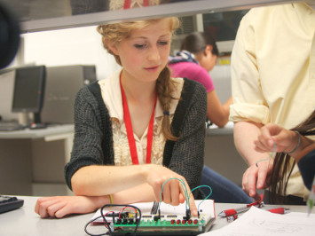
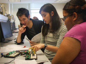
The following two photos show scholars working on Lab 1. The left photo shows a scholar demonstrating her two-input NAND gate assembled out of discrete transistors. The right photo shows a lab group working with a CURIE Academy Teaching Asistant to debug chaining several full-adders together.
|
|
Lab 1 Hardware
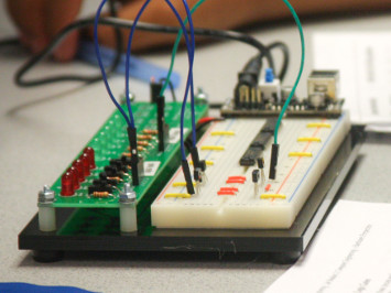
To support this lab, we designed, fabricated, and assembled two custom circuit boards. Although both boards are relatively simple, they made it possible for the scholars to quickly experiment with different circuits involving both discrete transistors and ICs.
The LED/switch board included support for five digital inputs (switch, red LED, current-limiting resistor, female header) and five digital outputs (green LED, current-limiting resistor, female header). The LED/switch board was combined with a full-size breadboard, a 5V regulated power supply, and a custom laster-cut acrylic base to create a simple prototyping platform. We pre-populated the breadboards with two discrete PMOS transistors, two discrete NMOS transistors, and three CD4000-series logic gates.
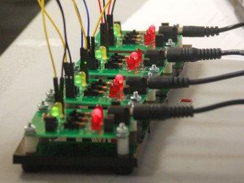
The one-bit full-adder board integrated a linear voltage regulator, four switches, five LEDs, current-limiting resistors, female header, and three surface-mount CD4000-series logic gates onto a single printed circuit board to implement the classic five-gate full-adder. These boards were designed so that they could either operate in "independent mode" with the carry input determined by an integrated switch, or in "chain mode" with the carry input coming from an external input via female header. This allowed the boards to be easily chained together to create increasingly larger multi-bit adders.
|
|